
Gigabit Communication Challenges Cable Technology: Semiconductors to the Rescue
Multi-gigabit communications present many challenges to cable manufacturers. How can bandwidths higher than 10Gbps required by new standards such as HDMI™ and DisplayPort be achieved over low cost cables? What are the core technical problems with achieving these high data rates and what technologies can be used to address them? How can manufacturers achieve solutions which are less dependent on copper pricing? How can reliability issues be resolved without the need to use thicker cables? Cable manufacturing techniques have evolved to try to meet the challenge, but semiconductor solutions are emerging as promising alternatives and can be expected to play a significant role in solving these issues.
This article explains the physical problems faced by cable manufacturers, in particular differential skew and limited bandwidth. The origins and implications for both problems are explained using eye diagrams. The article presents a silicon solution for these problems, discussing the challenges associated with circuits which automatically de-skew and the requirement for equalization to address the limited bandwidth problem. Data recovery is shown to be dramatically improved when adaptive de-skew and equalization is applied.
Cost-effective silicon embedded in a cable bulk-head, combined with low-cost manufacturing techniques (high AWG cables, etc), provide cable manufacturers with a competitive solution in terms of performance and cost.
Cable Manufacturers need to embrace semiconductor technology. Embedded silicon can answer the commercial and technical issues facing the industry today.
The Cable Problem
The main challenge for cable manufacturers is to solve the issue of propagation delay difference and high frequency suppression problems associated with the eternal need for increased data-rates. Propagation delay difference varies with cable length and dielectric constant and causes increased common-mode noise (cross-talk, EMI) and reduced transmission margin. High frequency suppression is a function of conductive loss (skin-effect and shield current) and causes increased rise times and reduced amplitude on the transmitted signal.
To combat these effects, manufacturers need to optimize the selection of cable type (moving away from STP to TWINAX or SCTC), dielectric performance (use mechanical foaming) and conductive material (use solid and not stranded material and move to low AWGs). These solutions are expensive and bring other challenges to the cable (bulkiness, weight, rigidness, solder-cracking in connector, etc). An alternative approach is to consider cost-effective embedded semiconductor solutions such as RedMere's MagnifEye™ Repeater, MagnifEye™ Switch and Cable MagnifEye™ solutions which solve these intra-pair skew and high frequency attenuation problems for different cable applications, allowing cable manufacturers to work with thin low-cost cables such as 36 AWG.
Intra-pair Skew
Intra-pair skew exists in all systems where differential signals are transmitted. It is caused by differences in transit times or electrical path lengths for the positive and negative parts of a differential signal. These transit time differences ("skews") or electrical path length differences are caused by tolerances in the cable manufacturing process. The phenomenon is not well known because twisted pair have only recently been used for Gigabit data rates. At these data rates cables of three meters and beyond have differential skew times that are significant portions of the data bit times.
To see where this "skew" time might come from we first note that signal propagation velocity along a twisted pair is approximately 0.71 times the speed of light which translates to approximately 47ps per cm. Thus for a ten meter cable the total delay is 47ns. Therefore a path length difference of just 1% within a ten meter cable causes an intra-pair skew of 470ps. We will show that this level of skew is disastrous in the context of 300-600ps bit-times. Figure 1 illustrates how a tiny change in the cable wrapping leads to a change in cable length, which then results in intra-pair skew.

Figure 1. Manufacturing quality affects path length in a twisted pair.
It is also important to note that even if the manufacturing process produces perfectly matched lengths, this does not guarantee zero skew. Cables and PCB materials can have non-uniform dielectric constants due to variation in thickness and material properties. This results in variation in propagation velocity, which also changes the effective path length. The skew problems discussed can be exacerbated by bending or compression of the cable, effects which are almost guaranteed in many application environments.
We have characterized hundreds of cables and found a wide variation in intra-pair skew ranging from 40ps on shorter cables up to 520ps on some 20 meter examples. Samples of cable measurements we have made are shown in Figure 2.
Figure 2. Measured intra-pair skew
The impact of skew for a TV receiver is to directly reduce the timing budget available to the data recovery circuit to extract the data. Figure 3 below shows the impact of 155ps of skew on a 3.4Gbps data eye through three meters of Twinax cable. This is the HDMI™ specification limit for the skew at the receiver end of a cable.
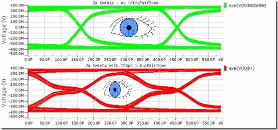
Figure 3. Eye diagram at 3.4Gbps showing zero skew (top plot) and eye diagram with 155ps of intra-pair skew (lower plot).
The top plot corresponds to a cable with zero skew and shows significant eye opening. This opening allows the data recovery block in the receiver sample the data over a 300ps window to decide whether a '1' or '0' is present. The lower plot shows that the addition of the 155ps of skew has reduced this valid data window to approximately 150ps thus making it virtually impossible for the data recovery block in the receiver.
Solution for Intra-pair Skew Problem
Redmere has patented a unique adaptive de-skewing technology to tackle the skew problem. This technology sits at the front end of the receiver chip and re-aligns the positive and negative portions of the differential signals. The re-alignment is done automatically using a combination of deep oversampling of the data bits and custom DSP. The result of this de-skewing block is seen below in Figure 4 where the top poor eye is reopened resulting in the data eye shown in the lower plot.
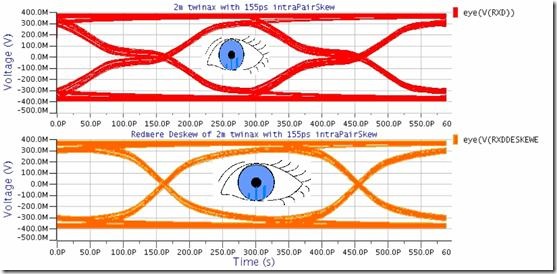
Figure 4. Eye diagram at 3.4Gbps showing degradation due to 155ps of skew (top plot) and improved eye diagram after processing by REDMERE's active de-skew circuitry (lower plot).
Inter Symbol Interference (ISI) or High frequency Attenuation
Because cables have multiple parallel lines there will invariably be some series inductance and parallel capacitance. These parasitic elements will filter the high frequency components of the signal. A measure of this effect is seen below in Figure 5. Here we see signal attenuation versus frequency for three and six meter cables.

Figure 5. Signal attenuation versus frequency for three and six meter Twinax cables.
When a signal is filtered by the cable, the data pulses of different lengths are shortened or lengthened and this degrades the data eye. This time domain degradation is seen in the eye diagrams of Figure 6 where we see the impact of passing data through a three meter Twinax cable (Top graph) and then further degradation when data is passed through six meters of Twinax cable.
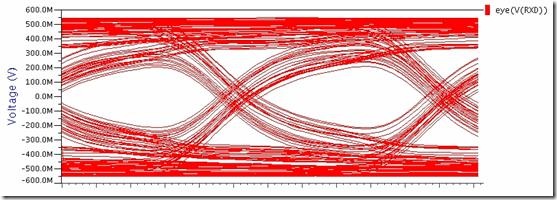
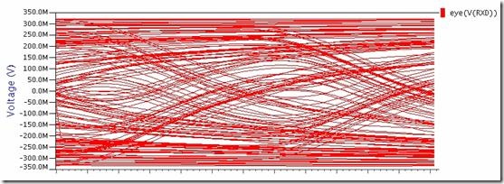
Figure 6. 3.4Gbps eye diagram at the end of three and six meters of Twinax cable.
Cable equalizers compensate for the high frequency loss by applying gain to the high frequency components of the received signal. This process is seen in Figure 7 where the cascade of the cable transfer function and the equalizer transfer function produce a unity gain or all pass transfer function.
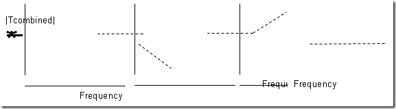
Figure 7. Cascading of cable transfer function with an equalizer transfer function produces unity gain over all frequencies.
If appropriate equalization is applied to the three meter data eye seen in Figure 6 then the resultant improved eye diagram is as can be seen in Figure 8.
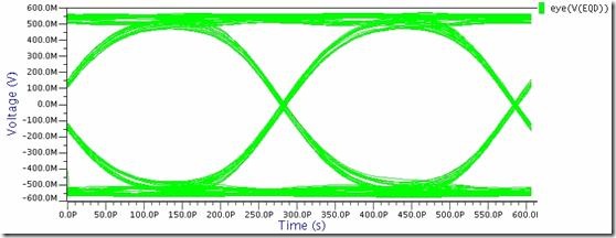
Figure 8. 3.4Gbps data with appropriate equalization showing improved eye.
If the same fixed equalization is applied at the end of a six meter cable then the result is a poor eye as shown in Figure 9. Thus the six meter cable is under-equalized and the level of eye closure here may well cause bit errors.
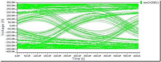
Figure 9. Poor 3.4Gbps data eye resulting from fixed equalization scheme applied to six meter cable.
For this reason, fixed equalization is not generally a quality solution and there is a requirement for tuning the equalization as the cable length changes. A simple implementation of this tuning process is referred to as programmable equalization. In this case, tuning of the equalizer chip is achieved by setting or resetting external pins. These pins enable the selection of different transfer functions for the equalizer. This process may work in certain situations with external test equipment selecting the correct settings on the chip, but the ideal solution is where the chip tunes the equalizer parameters itself. This is referred to as adaptive equalization. Adaptive equalization changes the transfer function of the equalizer to automatically cancel the attenuation caused by the cable.
It is also worth noting that some receiver chips with fixed equalization claim that they a suited for particular length cables. This claim, while partially true, ignores the variation associated with different cable technologies. This variation is clear from Figure 10 which shows different levels of attenuation found in 11 different five meter cables from different manufacturers.
Figure 10 Attenuation versus frequency measured in 11 cables from different manufacturers.
MagnifEyeTM Technology from Redmere
Our solution to the cable limitations is to do both adaptive de-skewing and adaptive equalization in tandem, i.e. using our patented MagnifEyeTM technology. This block sits at the front end of our HDMI products. MagnifEyeTM technology very effectively tunes the receiver to the specific cable connected. This gives the optimal reception of HDMI signals across longer cables and improves operating margins on shorter ones.
Figure 11 MagnifEyeTM Technology Block Diagram
The following section shows the impact of using both adaptive de-skewing and adaptive equalization. It is also clear from the following sequence that both are necessary.
Importance of Equalization and De-skew
The first scope shot (Figure 12) shows a closed eye when 2.275Gbps data is passed though a 15 meter cable with 300ps of skew.
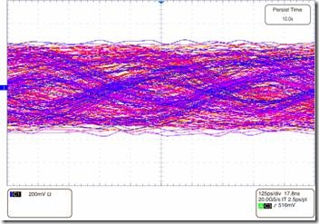
Figure 12 2.275Gbps Data at the end of 15 meters of cable with 300ps of skew.
Clearly there is no chance of recovering this data in this raw state. A standard analog front end would add equalization at this stage to improve the eye. The result of this can be seen below in Figure 13.
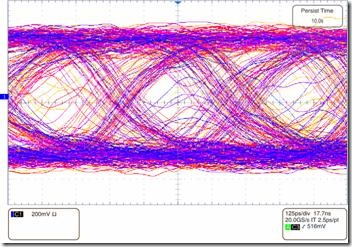
Figure 13 2.275Gbps Data at the end of 15 meters of cable with 300ps of skew with adaptive equalization applied
This signal has a wider eye opening but it is clear from the relative eye closure that the subsequent data recovery system would result in many bit errors. Standard front-ends available today are doomed to failure when required to deal with 300ps of skew as equalization is the only tool on offer. Fortunately MagnifEyeTM technology has another weapon in its arsenal; it also applies adaptive de-skewing to the same data, the result of which is shown in Figure 14.
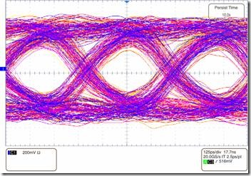
Figure 14 2.275Gbps Data at the end of 15 meters of cable with 300ps of skew with adaptive equalization and MagnifyeTM 's adaptive de-skewing.
Now the data has clear open eyes and is perfectly conditioned for the data recovery block.
Summary
This article has shown the challenges in sending up to 3.4Gbps through several meters of cable. Two of the key cable challenges, namely "differential skew" and "Inter symbol Interference" have been introduced and their impact on cable performance demonstrated. Both these problems reduce the valid data eye, but on cheaper cables the eye is completely closed and data is rendered unrecoverable. One solution to these problems is to use more expensive cable technology which will typically result in a thicker and less flexible cable. An alternative is to consider embedded silicon combined with lower cost bulk cable.
Redmere's patented MagnifEyeTM technology is such a solution, combining circuit solutions for each of the problems into one elegant core applicable to a variety of cable applications. Whether the application is a multi-port cable repeater, externally powered cable or a cable powered off internal power, MagnifEye™ provides optimal signal integrity for lowest cost cables. With MagnifEyeTM technology, cable manufacturers can deliver cable assemblies which meet the data requirements of today's market in a cost-effective manner.
About the authors:
Dr. John Horan ([email protected]), Chief Technology Officer and a Co-Founder of Redmere Technology. Previously he was an IC Architect with the Wireline Communications Division of Ceva Inc., based in Cork, Ireland. He has authored numerous technical papers and has had 6 US patents issued, with others pending.
Atsuhito Noda ([email protected]) is Director of New Technology Development for Molex's Global Micro Product Division and is based in Japan. He previously worked in Connector Engineering for 27 years and has 45 patents.
Deirdre Mathelin ([email protected]) is Product Manager for RedMere's HDMI™ semiconductor products and is based in Paris, Francea. She has 21 years semiconductor experience, having previously worked in semiconductor design for Infineon, ST Microelectronics and Ceva.
David McGowan ([email protected]), Applications Manager, based in Cork, Ireland, is responsible for RedMere's high-speed interface semiconductor application development. Prior to RedMere, David worked for Panasonic TV Group, Apple Computer and Ceva.
About RedMere Technology
Headquartered in Balbriggan, Ireland, RedMere is an innovator in driving architecture and semiconductor solutions for high speed multimedia interconnect applications for consumer electronics and personal computing markets. For more information, please visit www.redmere.com.
About Molex Incorporated
Molex Incorporated is a 69-year-old global manufacturer of electronic, electrical and fiber optic interconnection systems. Based in Lisle, Illinois, USA, the company operates 54 manufacturing facilities in 19 countries. The Molex website is www.molex.com.
Contact Details:
RedMere Technology Ltd.,2B Fingal Bay Business Park,
Balbriggan,
Co. Dublin,
Ireland
Tel: +353 1 841 0920
Fax: +353 1 690 4196
www.redmere.com
Molex Japan Co. Ltd.,
1-5-4 Fukamihigashi,
Yamato,
Kanagawa,
242-8585 Japan
Tel: +81 46 261 4500
Fax: +81 46 264 1470
www.molex.com