
articles
Digital Connectivity - A Tutorial

This is an excerpt from the HDTV Technology Review 2006 Report by Rodolfo La Maestra. If you are interested in the full version of this report, it is currently available from the HDTV Technology Review page.
The other parts in the series are:
Part 1: HDTV Technology Review, Part 1: Introduction
Part 2: 1080p into HDTV Displays
This tutorial article was drafted when DVI was starting to be implemented in HDTVs and first appeared on my 2003 HDTV report. Since then, it is customarily included in a separate section within each yearly report to provide the basic background about digital connections used in HDTV equipment. Additionally, on each annual report I use other sections to provide an update of how these connections are being implemented on audio and video equipment year after year, what type of problems they have, what functionally they facilitate, what is recommended regarding technical requirements when looking for a product (such as having HDCP compliance, a big issue in the 2003/4 reports), etc. In the 2006 report, HDMI is mentioned throughout the report, additionally there is a separate large section that covers the HDMI chips, the HDMI implementation, the trends of manufacturer's adoption, the specifications of the released versions, the issues surrounding incompatibility of HDMI suited products, the issues surrounding the new multi-channel audio hi-bit transported with HDMI, the implementation of content protection over the HDMI connection, etc. Each yearly report adds a new layer of the year regarding HDMI, as issues, as upgrades, as implementation trends, organizations involved with, manufacturers using it for 1080p sets and blu-laser players, etc. In other words, this except is just a section to get the reader familiarized with the basics of digital connectivity. For the complete picture, including wireless digital connectivity, please consult the annual reports.
DVI
The DVI (Digital Visual Interface) 1.0 specification was introduced in April 1999 by the Digital Display Working Group integrated by Silicon Image, Intel, Compaq, Fujitsu, Hewlett-Packard, IBM and NEC for the purpose of creating an digital connection interface between a PC and a display device. It is a connection with enough bandwidth for uncompressed HD signals. The 1.0 DVI specification is a point-to-point solution that supports video content but not audio. DVI uses the Transition-Minimized Differential Signaling (TMDS) protocol developed by Silicon Image. PanelLink is the Silicon Image's proprietary implementation of TMDS. The HDCP (High-bandwidth Digital Content Protection) 1.0 specification was developed by Intel with contributions from Silicon Image in February 2000 to protect DVI outputs from being copied by providing a secure link between a video source and a display device. HDCP offers authentication, encryption, and renewability. The Motion Picture Association of America (MPAA) endorsed HDCP as the standard for the secure transmission of HD signals over DVI. Most new DTV monitors and integrated displays have incorporated DVI or HDMI inputs, although on their first generation some panels were not HDCP compliant, now there is a large volume of H/DTV equipment that is. However, some displays were reported to have interoperability problems regarding DVI/HDCP or HDMI/HDCP. The DVI standard is able to handle single or dual link connections. A single-link connection supports up to UXGA resolution of 1600 x 1200 at 60 Hz. Dual-link connections provide bandwidth for resolutions beyond QXGA (2048 x 1536). According to DVI specs a single link has 165 MHz/pixels capacity for 3 channels, Red, Green and Blue, each channel could support up to 1.65 Gbps speed rate, or a total of 4.95 Gbps for the 3 channels (165 MHz x 30 bits x sec). Dual-link connections double that capacity to 330 MHz, with a speed-rate capacity up to 9.9 Gbps. The 1080i HD format has 1125 total lines of 2200 pixels x frame (active image 1080x1920), requiring 74.25 MHz/pixels (1125 x 2200 x 30fps). Each pixel contains data for RGB and is implemented by DVI with 30 bits (8 per each color plus another 6 for encoding). An HD 74.25 MHz/pixel signal would require 2.2 Gbps speed rate. A link of 3 channels supporting 165 MHz is sufficient for the 74.25 MHz HD 1080i signal without requiring the use of the second link, and will also be sufficient to transport a 1080p/60 frames x second signal at 148.5 MHz without requiring the second link. If the signal to be transmitted would be higher than the single link capacity of 165 MHz, it would require the use of a dual DVI link connection, each link will carry half of the signal; the second link cannot be used with just what is exceeding 165 MHz of the first link. For example, a 200 MHz signal would be carried with both links operating at 100 MHz each. HDMI uses the same 165MHz capacity per link; dual-link uses the B connector with the second link pins. DVI identifies and auto-configures the connected device. If source equipment is connected with DVI single link to a display configured as dual link DVI, the image will experience a lower resolution. Some first generation single link DVI cables use dual link connectors. DVI standard cables have typically a five-meter distance limitation, although with better quality wiring, such as fiber-optic, higher distances are possible. There are three types of DVI connectors: DVI-I (integrated), carries a single or dual-link digital signal, with an additional analog signal for legacy devices. The 29-pin DVI connector uses 24 pins for the digital data stream (12 for each link) and 5 pins (1 plus-shaped blade and 4 pins) to carry analog video and ground.
 DVI-I |
 DVI-D |
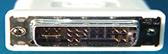 DVI-A |
IEEE1394
IEEE1394 is a digital interface conceived by Apple Computer in 1986, and it was called "Fire Wire" for its fast speed of operation. In 1995, the Institute of Electrical and Electronic Engineers (IEEE) adopted the serial bus as its standard 1394. Sony trademarked their name iLink for their implementation of the 1394 bus as a 4-pin connector. In March 2000, an updated specification was approved, the 1394a. The "a" standard supports speeds of 100Mbps, 200Mbps, and 400Mbps over a distance of 4.5 meters, and up to 63 peer-to-peer nodes/devices. In 2001, the IEEE 1394 "b" standard emerged as a network technology (rather than as serial bus); it is capable of moving data streams at faster speeds over longer distances than the original. The "b" standard specifications were intended to support up to 3,200 Mbps depending on the cable material, and permit the use of cabling materials not supported by the "a" standard. It supports speeds up to 100Mbps over 100 meters of Category 5 wiring, 400 Mbps over 100 meters of plastic optical fiber, and up to 3,200 Mbps (or 3.2 Gbps) over 100 meters of glass optical fiber. The "b" standard is compatible with the "a" standard; if an "a" device were plugged into a "b" component, the bus would deliver a maximum speed limited by the "a" standard (400Mbps). Each "b" device can be set up to 100 meters apart from the next in sequence, allowing the total network to be quite significant in cable length. The licensing fee for the use of the patented technology is $ 0.25 per system; chipsets are less than $5 each in volume. It supports hot swapping and plug-and-play, so a consumer's 1394 bus can recognize automatically a 1394 device when it is connected/disconnected, and reconfigure itself. The connection is now being used by a growing number of DTV equipment manufacturers for the transmission of compressed HD signals, such as D-VHS recording and networking DTV equipment. There are three types of cables used for 1394. The 6-conductor type has two separately shielded twisted pairs for data and two power wires in an overall shielded cable with 6-pin connectors on either side. The 4-wire cable uses two separately shielded data cables without power wires in an overall shielded cable with 4-pin connectors on either end. The third type of cable uses either type of actual cable, with a 6-pin connector on one side, and a 4-pin connector on the other side of the cable. The 4-pin connector is more common on digital video camcorders and other small external devices because of it's small size, while the 6-pin connector is more common on PC's, external hard drives due to it's durability and support for external power for 1394 peripherals.
 6-pin female connector above left 4-pin female connector above right |
 The 6-pin male connector |
 4-pin male connector |